The greatest research looks beyond what’s known.
It has a mind for discovery and progress – to solve global challenges and create positive change. This is the kind of research we believe in at the School of Mechanical and Mining Engineering.
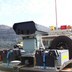
The work we do is organised around four centres: Advanced Materials Processing and Manufacturing (AMPAM), Centre for Hypersonics, Multiscale Energy Systems, and Future Autonomous Systems and Technologies.
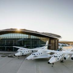
Our research is geared towards building sustainable societies, fuelling technological advancements in the aerospace and defence industries, transitioning to 21st century energy systems and navigating the challenges of a digitally-disrupted future.

Our research in action
Our researchers hit the headlines for their significant contributions to the fields of mechanical and mining engineering. See our latest research news.
Our research impact
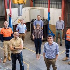
Find a researcher or supervisor
Search researchers by name, research group, or explore our research capabilities.