Hubert CHANSON (h.chanson@mailbox.uq.edu.au)
M.E. (Grenoble), ENSHM Grenoble, INSTN (Saclay), PhD (Canterbury),
DEng (Qld), Eur.Ing., MIEAust., MIAHR
Department of Civil Engineering, The University of Queensland, Brisbane
QLD 4072, Australia
This lecture was presented as an invited seminar at Kyoto University, Disaster Prevention Research Institute, "Air entrainment by plunging jets" & "Current expertise and experience on stepped channel flows", by H. CHANSON on 27 April 1999 (Kyoto, Japan) {http://www.uq.edu.au/~e2hchans/dpri/}. Since the site was regularly updated. The last revision was made in May 2001.
| Index (Kyoto lectures) |
|
|
| Reprints of Research Papers |
|
Copyright
You may use this information for no commercial
use only. However the copyright remains attached to the author {Dr Chanson}.
Stepped channels and spillways are used since more than 3,000 years. Recently, new construction materials (e.g. RCC, gabions) have increased the interest for stepped chutes. The steps increase significantly the rate of energy dissipation taking place along the chute and reduce the size of the required downstream energy dissipation basin. Stepped cascades are used also for in-stream re-aeration and in water treatment plants to enhance the air-water transfer of atmospheric gases (e.g. oxygen, nitrogen) and of volatile organic components (VOC).
The paper reviews the hydraulic characteristics of stepped channel flows. Basic equations are developed and discussed. Then the writer relates the historical development of stepped chutes. Then he discusses the parallel development of dropshaft cascades in Roman aqueducts and stepped fountains in the formal water gardens of the 16th to 18th centuries. Later he comments on past failures of stepped chutes.
Recent advances in technology have permitted the construction of large dams, reservoirs and channels. These progresses have necessitated the development of new design and construction techniques, particularly with the provision of adequate flood release facilities and safe dissipation of the kinetic energy of the flow. The latter may be achieved by the construction of steps on the spillway. A stepped chute design increases significantly the rate of energy dissipation taking place along the spillway face, and eliminates or reduces greatly the need for a large energy dissipator at the toe of the chute.
In this paper, the author reviews first the basic hydraulic characteristics of stepped channels. Then he discussed the historical development of stepped spillways for the past 3,000 years ! The paper is based largely upon the writer's experience as a researcher, lecturer and consultant. He wrote three books (CHANSON 1995a, 1997a, 1999), gave several short courses on the hydraulic design of chutes and spillways (incl. stepped channels) and he has introduced the stepped spillway design in undergraduate and postgraduate subjects.
3.1 Presentation
Stepped channels may be characterised by two types of flow : nappe
flow and skimming flow (Fig. 1). At low flow rates and for relatively large
step height, the water bounces from one step onto another as a succession
of free-falling nappes (i.e. nappe flow). Dominant flow features include,
at each drop, an enclosed air cavity, a free-falling jet and nappe impact
on the downstream step. Most energy dissipation takes place by nappe impact
and in the downstream hydraulic jump.
Fig. 1 - Photographs of nappe flow and skimming flow (more photographs at http://www.uq.edu.au/~e2hchans/photo.html#Uq_step_chu)
Fig. 2 - Onset of skimming flow : comparison between model data, CHANSON's
(1994) correlation and Equation (1) (Not enclosed)
At larger flow rates, the flow skims over the step edges with formation of recirculating vortices between the main stream and the step corners. Most energy is dissipated in maintaining the recirculation in the step cavities.
The transition between nappe and skimming flow is related to the flow
rate, chute slope, step geometry and local flow properties at each step.
In uniform equilibrium flows down prismatic rectangular channels, a limiting
condition for skimming flow is :
![]() Skimming flow conditions (1)
Skimming flow conditions (1)
where dc is the critical flow depth, h is the height and l is the step length (Fig. 2). Equation (1) is limited to flat horizontal steps for h/l ranging from 0.2 to 1.4, it characterises the onset of skimming flow for uniform or quasi-uniform equilibrium flows and its accuracy is within +/- 30%. For accelerating or decelerating flows (i.e. rapidly varied flows), Equation (1) is inaccurate and a more complete analysis is required (e.g. CHANSON 1996).
3.2 Skimming flow
In a skimming flow, the free-surface on the upper steps is clear and
transparent. A turbulent boundary layer develops however along the chute
invert. When the outer edge of the boundary layer reaches the free-surface,
free-surface aeration takes place (Fig. 3). Downstream the flow becomes
fully-developed and gradually-varied. Further downstream the flow reaches
uniform equilibrium.
At the inception point of air entrainment, the main flow characteristics
are the distance LI from the crest (measured along the invert) and the
flow depth dI measured normal to the channel invert. Model and prototype
data indicate that LI and dI are best correlated by (CHANSON 1995a) :
![]() (2)
(2)
![]() (3)
(3)
The re-analysis of model and prototype data indicates consistently that
the dimensionless distance from crest and flow depth increase with increasing
dimensionless discharge (Fig. 4). Further the rate of boundary layer growth
is greater on stepped channels than on smooth chutes. The experimental
results are basically independent of the type of crest profile (CHANSON
1995a).
Fig. 3 - Skimming flow regions (Not enclosed)
Fig. 4 - Position of the inception point of air entrainment : LI/(h*cosq)
as a function of F* (Not enclosed)
There is little information on the flow characteristics in the gradually-varied
flow region. Numerical modelling (e.g. backwater calculations) is inaccurate.
Complete flow calculations may be conducted only at uniform equilibrium
(CHANSON 1995a) when the weight component in the flow direction equals
the bottom friction. It yields :
![]() Uniform equilibrium flow (4)
Uniform equilibrium flow (4)
where Vo is the normal velocity, f the Darcy-Weisbach friction factor and DH the hydraulic diameter.
There is some controversy on friction factor estimate for stepped channel with skimming flow. Model and prototype data exhibit little correlation and most clear-water flow data are scattered between 0.09 £ f £ 10. A value {f = 1.0} was earlier proposed although "the author recommends to use f = 1.0 as an order of magnitude of the friction factor for skimming flow on steep slopes" (CHANSON 1995a). A recent study derived an analytical formulation leading to f = 0.2; the result compared well with new large-size model data (CHANSON, YASUDA and OHTSU 2000, CHANSON 2000b).
Design calculations
On the stepped chute, both the flow acceleration and boundary layer
development affect the flow properties significantly. The complete flow
calculations can be tedious and most backwater calculations are not suitable.
CHANSON
(1999) proposed a pre-design calculation method which provides a general
trend which may be used for a preliminary design (Figure No. 5). Ideally,
the maximum velocity at the downstream chute end is Vmax. In
practice the downstream flow velocity V is smaller than the theoretical
velocity Vmax because of friction losses. In Figure No. 5, the
mean flow velocity is plotted as V/Vmax versus H1/dc
where H1 is the upstream total head and dc is the
critical depth. Both developing flow calculations and uniform equilibrium
flow calculations are shown. Fitting curves must be plotted to connect
these lines.
Fig. 5 - Residual flow velocity
at the downstream end of a stepped chute with skimming flow - Comparison
with smooth-chute calculations and data (after CHANSON
1999, http://www.uq.edu.au/~e2hchans/reprints/errata.htm)
Effects of air entrainment
Downstream of the inception point, a substantial amount of air is entrained.
The air concentration profiles may be compared with a simple
diffusion model developed for and validated with prototype and model
smooth-chute data (CHANSON 1995b):
 (5)
(5)
where tanh is the hyperbolic tangent function, y is the distance normal to the channel bed and Y90 is the characteristic distance where C = 90%, D' is a dimensionless turbulent diffusivity and K' is an integration constant. D' and K' are functions of the mean air content Cmean only. The mean equilibrium air concentration Cmean is as a function of the channel slope q (CHANSON 1995a). For slopes flatter than 50 degrees, it may be estimated as : 0.9*sina.
Equation (5) was tested successfully on model and prototype data (RUFF and FRIZELL 1994 & BAKER 1994 respectively). CHANSON and TOOMBES (1997) demonstrated the analogy between free-surface aeration in smooth and stepped chutes. Further the observed values of mean air content in stepped chute flows were close to the uniform equilibrium mean air concentration in smooth chutes : i.e., (Cmean)e = 0.27 and 0.36 for a = 18.4 and 26.6 degrees respectively (WOOD 1983, CHANSON 1997a). The data of BAKER (1994) give Cmean = 0.15 to 0.23 with a 18.4 degree slope, and the data of RUFF and FRIZELL (1994) indicate Cmean = 0.33 at the end of the 26.6-degree slope channel.
Practically free-surface aeration affect the flow properties because
of flow bulking and drag reduction. For uniform equilibrium flows, the
flow bulking may be estimated as :
![]() (6)
(6)
The characteristic depth Y90 takes into account the flow bulking caused by the air entrainment and it may be used as a design parameter for the height of the chute sidewalls.
Drag reduction induced by free-surface aeration results from the interactions
between the entrained air bubbles and the turbulence next to the invert.
It may be estimated as :
 (7)
(7)
where f is the clear-water friction factor and fe is the air-water flow friction factor. Equation (7) was validated with model and prototype data (e.g. CHANSON 1997a). It predicts a departure of the aerated friction factor fe from the non aerated value f for mean air concentrations larger than 20% and the residual energy may be strongly underestimated (if the effect of air entrainment is neglected). A recent investigation (CHANSON and TOOMBES 2001) demonstrated that Equation (7) is valid in skimming flows down stepped chutes. It is most important that design engineers take into account flow aeration to estimate the residual energy and to dimension stilling basins downstream of stepped chutes.
3.3 Nappe flow
At low flow rates, the water bounces from one step onto the next one.
Technically the author defines the nappe flow regime as a flow situation
consisting of free-falling jets in presence of nappe ventilation.
At very low flow rates, the flow at each step consists of the free-falling
nappe, nappe impact followed by a fully-developed hydraulic jump [Nappe
flow regime NA1]. The kinetic energy of the flow is dissipated at nappe
impact and in the hydraulic jump, and the head loss at each step equals
the step height. This flow pattern occurs for (CHANSON 1994):
![]() Nappe flow with fully-developed hydraulic jump [NA1] (8)
Nappe flow with fully-developed hydraulic jump [NA1] (8)
For ventilated air cavities, all the flow properties may be deduced from analytical, semi-analytical and experimental studies (CHANSON 1994, 1995a pp. 44-49).
For a given chute geometry, the drop length of the nappe increases with increasing flow rate and the hydraulic jump flow interferes with the downstream overfall (nappe flow with partially-developed hydraulic jump [NA2]). A nappe flow without hydraulic jump might occur also for relatively large discharges before the apparition of skimming flow. The flow properties of nappe flow regimes NA2 and NA3 are not well understood.
Flow patterns of nappe flow regime NA3
A recent investigation (CHANSON and TOOMBES 1997) highlighted three-dimensional
flow patterns in a nappe flow without hydraulic jump [NA3]. At each step
the nappe impact induces significant water splashing and jet deflection,
followed by the propagation of oblique shock waves (i.e. cross-waves)
intersecting further downstream on the channel centreline. More sidewall
standing waves are observed at the impact of the nappe along the sidewalls.
The maximum height of the wall standing waves might be as large as the
step height.
Altogether the flow is three-dimensional. The interactions between the free-falling nappes, the shock waves and the sidewall standing waves are significant and they affect the design of the chute sidewalls.
3.4 Discussion
The above development provides some information on stepped flow properties.
It must be stressed however that equations (1) to (8) are valid ONLY for
stepped channels with flat horizontal steps in absence of lateral inflow
and for prismatic channels of rectangular cross-section (both stepped chute
and stilling basin channel). Further nappe flow properties may be estimated
only for nappe flow with fully-developed hydraulic jumps and ventilated
air cavities.
No systematic study has been conducted with pooled steps, inclined steps or non-rectangular cross-section channels. Some experimental works suggested that nappe flows with non-ventilated cavities exhibit significantly different properties from ventilated cavity nappe flows.
4.1 Presentation
The world's oldest stepped spillway is presumably the overflow
stepped weir in Akarnania, Greece, built around B.C. 1,300 (Fig. 6A).
The weir is an earthfill embankment, 10.5-m high with a 25-m long crest
(KNAUSS 1995). The downstream slope is stepped (14 steps) with masonry
rubbles set in mortar. The mean slope is about 45 degrees, varying from
39-degrees down to 73-degrees and the step height ranges from 0.6 to 0.9-m.
Another series of ancient stepped spillways are those of the two Khosr River dams (or Ajilah dams), in Iraq. The dams were built around B.C. 694 and remains of the structures are still standing. Later the Romans built stepped overflow dams in their empire : remains are found still in Syria, Libya and Tunisia. After the fall of the Roman empire, Moslem civil engineers gained experience from the Nabataeans, the Romans and the Sabaens. They built dams with stepped overflow in Iraq, Saudi Arabia and Spain. At a later period, Spanish engineers continued to use the Roman and Moslem structures. They designed also new weirs and dams with overflow stepped spillways. Between 1400 and 1850, the expertise of Spanish engineers was exceptional and it was exported to America. They built several stepped overflow dams in Central Mexico during the 18th and 19th centuries, and some were still in use in the 1950s.
Stepped spillways were also built in Europe : France, United Kingdom, Germany. Most structures were masonry construction, unlined rock cascades and timber crib structures (e.g. CHANSON 1995a).
Most large stepped cascades were masonry structures. Interestingly two unusual structures were built in Australia. The Malmsbury cascade was a composite structure (crib and masonry) while the Gold Creek dam spillway was made of non-reinforced concrete, a world first according to CHANSON and WHITMORE (1998).
Fig. 6A - Old
stepped weir (dam) in Akarnania, Greece B.C. 1,300 [Courtesy of Professor
KNAUSS]
Dam : 10.5-m height, weir crest length : about 25 m, earthfill structure,
about 14 steps, mean stepped slope : about 45º (from 39º down
to 73º), step construction : masonry rubbles set in mortar, h = 0.6
to 0.9-m (KNAUSS 1995)
Three-quarter
view with watermill in foreground and new road ramp over the weir
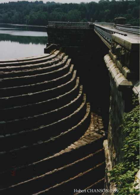
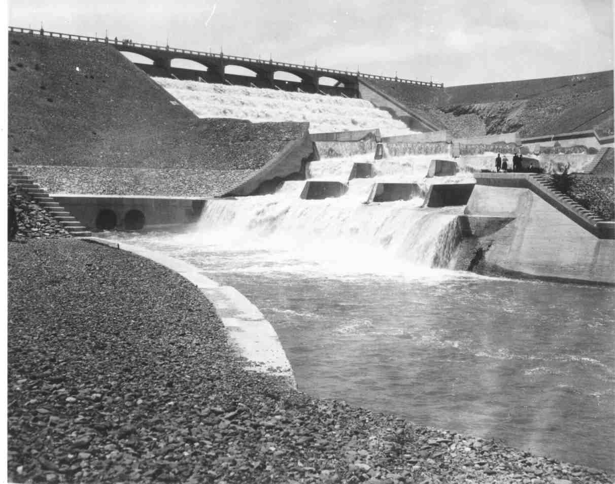
Fig. 6B - New
Croton dam (USA, 1906) : view
of the spillway from right bank, in 1999 [Courtesy of Mrs J. HACKER]
Dam height : 90.5 m, maximum discharge : 1,550 m3/s, h = 2.13 m, stepped
slope : 53º
Note the masonry dam on the right, and the bridge connecting the dam
crest to the right bank over the spillway weir
More photographs of ancient stepped spillways ....
4.2 Discussion
By the fall of the 19th century, overflow stepped spillways were selected
frequently to contribute to the dam stability and to enhance energy dissipation.
Most structures were masonry and concrete dams with a downstream stepped
face reinforced by granite blocks (e.g. Goulburn weir). Earth embankments
were usually equipped a lateral spillway (e.g. Val House dam, Gold Creek
dam). Some dams were equipped with stepped rocklined spillways (e.g. Ternay
and La Tâche dams). Others had a lateral spillway (e.g. Pas-du-Riot
dam). The spillway of the New Croton dam (1906) is probably the first stepped
chute designed specifically to maximise energy dissipation (Fig. 6B).
In the first part of the 20th century, the interest for stepped cascades dropped : "Cascades were formerly used a great deal. [... but] Cascades have seldom lived up to their expectations, and have seldom justified their high cost. [...] Considerably cheaper means of dissipating energy are known today" (SCHOKLITSCH 1937, p. 913). Indeed new progress in the energy dissipation characteristics of hydraulic jumps (e.g. BAKHMETEFF and MATZKE 1936) favoured the design of stilling basins downstream of chutes and spillways. Stilling basins allowed larger energy dissipation and smaller structures. Altogether, the concept of downstream stilling basins contributed to cheaper hydraulic structure constructions.
Recently (in the 1970s) design engineers have regained interest for stepped spillways. The trend was initiated by the introduction of new construction materials : e.g. roller compacted concrete (RCC), strengthened-mesh gabions. Over the past two decades, several dams have been built with overflow stepped spillway around the world. For example, the embankment overflow stepped spillways in Russia made with precast concrete blocks {http://www.uq.edu.au/~e2hchans/over_st.html}.
5.1 Introduction
CHANSON (1995a, pp. 24-36) argued that drop structures and stepped
profiles were also used in some early irrigation systems in the Middle-East
and in the Americas. Drop structures were introduced to dissipate the flow
energy and to accommodate with a steep topography. A related form is the
terrace irrigation system found in high-mountain areas (e.g. in the Cusichaca
valley, Peru). One of the most ingenious systems was the Quishuarpata canal
(Peru). The canal included two 100-m long steep chutes, designed with small
steps (h = 1 to 3 cm) along the chute course and larger steps near the
downstream end. No stilling ponds were used.
A related form of "water supply" systems was the aqueducts built by the Romans. The hydraulic expertise of Romans has contributed significantly to the advances of science and engineering in the Antiquity and up to the end of the Middle Age. The aqueducts at Rome, in France and North Africa, for example, left an indelible trace of this savoir-faire (e.g. ASHBY 1925, RAKOB 1974).
Roman aqueducts were designed with flat longitudinal slopes : i.e., 1 to 3 m/km in average typically. Short sections however had a steep-gradient : i.e., up to 78% (CHANSON 2000a). Current knowledge and field observations suggest primarily three types of design : steep "smooth" chutes, stepped channel and the dropshaft cascade (Fig. 7). The stepped chute design was common also with dam spillways (see above) and Roman engineers built several significant stepped spillways. But the dropshaft cascades were a very particular design.
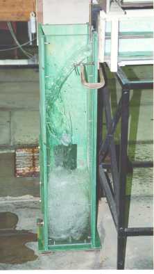
Figure 7 - Dropshaft
cascade in Roman aqueduct : dropshaft
model in operation
5.2 Dropshaft cascades
Roman engineers built two types of dropshafts : dropshaft cascades
along the main branch of aqueducts, in France and Algeria predominantly,
and interconnection shafts from newer higher channels to older aqueducts
(e.g. at Rome). The latter had a specific purpose (i.e. water redistribution)
and their design was a concourse of circumstances (i.e. proximity of an
older aqueduct) rather than a specific engineering feature of the newer
aqueduct.
Dropshaft cascades were used in steep topography predominantly : e.g., Recret, Vaugneray and Grézieu-la-Varenne, Yzeron aqueduct (Lyon, Fr.), Montjeu, Autun aqueduct (Fr.), Rusicade (Alg.), Gunudu (Alg.). Sometimes, combination of steep chutes and dropshaft were used : e.g., Chabet Ilelouine, Cherchell aqueduct (Alg.), Beaulieu aqueduct (Aix-en-P, Fr.). From a sole hydraulic perspective, the dropshaft cascades might have been used for : (1) a vertical drop in invert elevation, (2) kinetic energy dissipation, and (3) flow aeration.
In the first application, a dropshaft allows the connection between
two flat conduits, located at different elevations, along a very short
distance : i.e., the shaft length. By contrast, a steep chute would require
a horizontal distance equals to the drop height times the bed slope. The
second application of dropshaft is the dissipation of the kinetic energy
of the flow. Such a design is still used today (e.g. APELT 1984, RAJARATNAM
et al. 1997). It must however be optimised as a function of the drop height,
shaft geometry and flow rate. With non-optimum flow conditions, scour and
erosion may take place, and these are unacceptable. A third application
is the aeration of the flow : e.g., re-oxygenation. Recent investigations
of air bubble entrainment at vertical rectangular dropshaft highlighted
the high rate of bubble entrainment in the shaft pool (e.g. ERVINE and
AHMED 1982).
5.3 Hydraulics of Roman dropshafts
A hydraulic study of Roman dropshaft showed the soundness of the concept.
A comparison with modern drop structures and vortex shafts suggested that
Roman dropshafts operating at low flow rates (i.e. regime R1) were most
efficient energy dissipators, by modern standards (CHANSON
2000a).
Compared with modern designs, Roman dropshafts exhibited unusual shapes : i.e., a deep wide shaft pool. Modern dropshafts do not include a pool, the shaft bottom being at the same elevation as the downstream channel bed, to minimise construction costs. At Roman aqueducts, the pool of water acted as a cushion at the nappe impact, and the disposition contributed to prevent scour of the shaft bottom. The shaft pool facilitated further the entrainment (by plunging jet) of air bubbles deep down, maximising the bubble residence time and hence the air-water gas transfer. The design contributed successfully to an enhancement of the DO content (dissolved oxygen content).
6.1 Presentation
In decorative architecture, waterfalls and cascades are used to please
the eye and the ear. They provide a focal point as well as sounds generated
by water splashing and cascading. Cascades can enhance the perception of
a site and focalise public attention on a particular setting (e.g., a theatre
at Le Bosquet
des Rocailles, Versailles). Stepped fountains and water staircases
combine simple architectural forms with a large amount of splashing and
'white waters'. The stepped geometry is further well suited to a steep
topography : i.e., La Grande Cascade de Saint-Cloud on a steep hill slope
facing Paris and the Seine river, l'Escalier
d'Eau du Château du Touvet on the flank of the Chârtreuse
mountain range in the French Alpes. Rushing waters along stepped cascades
may reflect some parallel with mountain rivers or natural cataracts : e.g.,
the cataracts of the Nile river, the Zambesi rapids in Africa or the Rhine
waterfalls (CHANSON 1995a, pp. 156-163).
6.2 History of stepped fountains
A fountain is a spring of water issuing from the earth and it is a
source of public water in cities. Over the centuries, fountains and cascades
have been used also as recreational and artistic features (Table 1). Greek
and Roman architects designed fountains. The Muslims developed also a strong
artistic sense for water gardens. The Mongols gained expertise from them
after the conquest of Persia. Their descendants, the 'Mughals', imported
the Moorish garden expertise in India where they built superb water gardens
in Kashmir (CHANSON 1998b).
In Europe, the tradition of stepped cascades appeared (or re-appeared) in Italy around the Renaissance period (e.g. Villa d'Este, Tivoli). However the French gardeners became the Masters of stepped cascade design during the 17th century (e.g. Marly, Sceaux, St-Cloud, Versailles). Their work influenced all the European countries for the next 200-years. Among the French designs, the gardens of Le Château de Versailles and of Le Château de Marly were most renown (Fig. 8). The park included several magnificent cascades (e.g. La Rivière) which were copied all over Europe (e.g. at Chatsworth, UK, Peterhof, Russia, La Granja, Spain, and Wilhemshöhe, Germany). At Peterhof one cascade is called Marly indeed.
It is worth noting some design similitude between the Mughal and French gardens. PLUMPTRE (1993) noted the similarity of garden architecture between the Taj Mahal completed in 1654 and Vaux-le-Vicomte (completed in 1656). The parallel can be further extended to stepped cascade design : e.g., Nishat Bagh (around 1640) and Rueil (1638), Achabal (around 1620) and Marly (1687). The famous French and Mughal gardens were completed only few years apart albeit the absence of direct contact between the French kingdom and the Mughal empire. But while the Taj Mahal and Nishat Bagh were the ultimate achievements in Mughal art, Vaux-le Vicomte and Rueil were the precursors of the 17th/18th century European water gardens and cascades. After the 18th century, the interest for the great cascades seemed to fade away. However in the cities, stepped fountains have been continuously built since the Roman time up to now (Table 1).
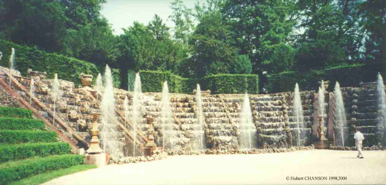
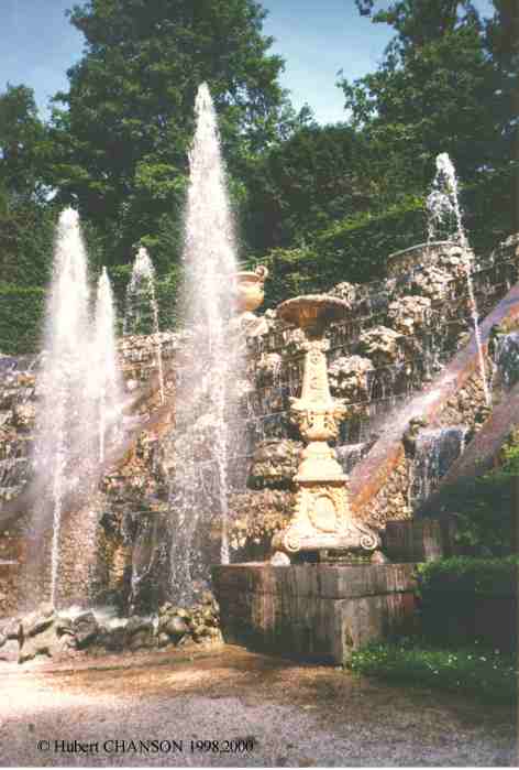
Fig. 8 - A stepped fountain : Bosquet des Rocailles, Château de
Versailles (France, 1683) - Photo No.
1 : panoramic view. Photo No. 2
: water jets and cascading waters. Photo
No. 3 : details (Photographs taken during the Grandes Eaux on 20 June
1998).
Le Bosquet des Rocailles (or Bosquet de la Salle de Bal) was built
between 1680 and 1683 by J. MANSART in the gardens of the Chateau de Versailles
(France). The sculptures were by Pierre LEGROS (1629-1714) and Benoît
MASSOU (1627-1684). The cascade comprises : 5 8-steps fountains, 8 7-steps
fountains, and 4 4-steps fountains. The Bosquet itself was designed by
LENOTRE in 1680. The scene was modified in 1690 and flowers were introduced
in 1691.
More photographs of staircase fountains and formal water gardens ...
More on the Formal
Water Garden ...
6.3 Discussion
By their size and characteristics (Table 1), the stepped fountains
of the 17th and 18th centuries compared with contemporary stepped spillways.
La Rivière at Marly, 300-m long, was larger than any existing spillway
! The cascades at La Granja, Palazzo Reale (Spain) et Peterhof (Russia)
were also larger than most spillway structures.
During Roman and Moslem periods, it is believed that there was no major distinction between architectural hydraulics and spillway hydraulics. But their successors (the Spaniards and Moghols) did not continue the tradition. In Spain, several stepped spillways were built (e.g. CHANSON 1995a) but the stepped fountain expertise disappeared. The Spanish king Philip V had to bring a French architect, FRÉMIN, to design La Granja cascade despite the local stepped spillway expertise! In Russia, the tsar Peter the Great selected a French designer for Peterhof cascades while he used the services of a Dutch engineer, G.W. HENNIN, to build dams and stepped spillways (e.g. Kamenskii dam).
In recent times, the concept of multi-purpose cascades was developed. Near Chicago (USA), five artificial cascades were designed along a waterway system to help the re-oxygenation of the polluted canal (ROBISON 1994). The waterfalls were landscaped as leisure parks and combined aesthetics and water quality enhancement. In Japan and Taiwan, stepped river training are combined with attraction parks. A related concept is the fish ladders designed as both aesthetical cascades and fishways in Japan and North-America.
Table 1 - Characteristics of stepped cascades, water staircases and
public fountains
|
|
|
|
|
|
|
|
|
|
|
|
|
|||||
|
|
|
|
|
|
|
|
|
| Garden cascades | |||||||
| Villa d'Este, Tivoli, Italy 1550-1568 |
|
Water staircases, stepped cascades and fountains. | Designed by P. LIGORIO [JE]. | ||||
| Achabal, India around 1600-1620 | Large water staircase. | Built by Emperor JAHANGIR. W ~ 21 m. | |||||
| Grande Cascade de Rueil, France 1638 (demolition in 1720) | About 30 steps. | Designed by T. FRANCINI for Cardinal de RICHELIEU. Replaced in 1720 by a lawn. [HE] | |||||
| Nishat Bagh ('Garden of Gladness'), India around 1620-1640 | Long water staircase [PL]. | Created by Yamin Al-Aula Asaf KHAN, brother of Nur JAHAN during the Mughal period. | |||||
| La Grande Cascade de Saint-Cloud, France | |||||||
|
Upper cascade, 1667
|
|
|
|
6 series of 3 flat steps (l=0.4 m) and 1 long step (l=1.9 m). | Designed by A. LEPAUTRE. 2 parallel cascades (W = 2 m) separating drops and waterfalls. | ||
|
Lower cascade, 1697
|
|
Pooled steps. | Designed by J. MANSART. | ||||
| Les Grandes Cascades de Sceaux, France 1677 |
|
|
|
Pooled steps with rounded crest. | Designed by A. LE NÔTRE for the Minister J.B. COLBERT. | ||
| Bosquet des Rocailles, Versailles, France 1683 |
|
5 8-steps fountains, 8 7-steps fountains, & 4 4-step fountains. | Also called Bosquet de la Salle de Bal. Designed by J. MANSART. Nappe flow regime (pooled steps). | ||||
| Les Cascades de Marly, France | Designed by J. MANSART for King Louis XIV. | ||||||
|
La Rivière, 1687 (demolition in 1728)
|
|
|
|
Pooled steps | About 300-m long. Replaced in 1728 by Le Tapis Vert. | ||
|
La Cascade de la Rivière, 1687
|
|
|
Pooled steps. | ||||
|
Les Nappes
|
|
Pooled steps | Landscaped with rocks. | ||||
|
La Cascade Champêtre
|
|
|
4 series of 9 pooled steps | Also called La Cascade Rustique or Les Cascades Champestres. | |||
|
L'Abreuvoir, 1698
|
|
Pooled step. | |||||
| Chatsworth's Great Cascade, Derbyshire, UK 1696 | Horizontal steps . | Designed by GRILLET based upon La Rivière de Marly [JE]. | |||||
| Wilhelmshöhe, Hesse-Kassel, Germany 1701-1713 (originally called Kassel-Weissenstein) | Designed by G. GUERNIERO [PL]. 240-m long, 10.7-m wide. | ||||||
| Peterhof's Grand Cascade, St Petersburg, Russia 1704-1715 |
|
Pooled steps followed by waterfalls. | Designed by J.B.A. LE BLOND for Tsar Peter I the Great. Inspired by Marly's cascades. | ||||
| La Granja, Segovia, Spain 1720 | Built for King Philip V of Spain. | ||||||
|
La Cascada
|
|
Pooled steps. | Built by R. FRÉMIN. Inspired by La Rivière, Marly (W~10m). | ||||
|
Carrera de Caballos
|
|
Cascading pools. | Include 114 water jets. | ||||
| Palazzo Reale, Caseta, Italy 1752-1770? | Great cascade (12 steps) and water staircases. | Designed by L. VANVITELLI for King Charles III of Naples. Inspired by La Granja. [PL] |
|
|
|
|
|
|
|
|
|
|
|
|
|
|||||
|
|
|
|
|
|
|
|
|
| Ancient public fountains | |||||||
| Fontaine des Innocents, Paris, France 1549 |
|
|
4 7-step cascades. Pooled steps. | Designed and sculpted by J. GOUJON. Nappe flow regime. | |||
| Cascade du Trocadéro, Paris, France 1878-1935 |
|
|
|
7 pooled steps followed by a 3.5-m high drop. | Designed by J. BOURDAIS and G. DAVIOUD for Universal Exposition in Paris. Demolished in 1935. | ||
| Fountain of Porte de St-Cloud, Paris, France 1936 | 2 circular stepped cascades. | Designed by R. POMMIER, J. BILLARD and P. LANDOWSKI. | |||||
| Modern public fountains | |||||||
| Bank of China, Hong Kong |
|
|
|
Flat steps inclined downwards. | W = 0.25 m. l = 0.13 m. | ||
| Central Plaza, Hong Kong | Flat steps, drops and pooled steps. | Nappe flow regime. Circular fountain. | |||||
| Chater Garden, Hong Kong |
|
|
Pooled steps. | Square fountain. Thin free-falling nappes. | |||
| City riverside fountain, Brisbane, Australia |
|
|
|
|
|
Horizontal steps | Nappe flow regime. W=2 to 3m. |
|
|
|
Horizontal steps. | W = 5.5 up to 7.5(?) m. | ||||
| Keio Plaza Hotel, Tokyo, Japan |
|
Pooled steps. | Nappe flow regime. | ||||
| Peak tramway fountain, Hong Kong) |
|
|
Horizontal steps. | Skimming then nappe flow regime. W = 0.8 to 5 m. | |||
| Taipei world trade centre fountain, Taiwan |
|
|
|
Pooled steps. | Succession of overfalls. No hydraulic jump. | ||
| Multi-purpose cascade | |||||||
| Calumet waterway re-aeration cascades, Chicago, USA |
|
|
|
|
Pooled steps. | 5 re-oxygenation cascades. Nappe flow regime. | |
| Nikita Prefecture park, Japan | Flat steps built from stones. | Stepped river training & vertical drops in an attraction park. |
References : Present study, CHANSON (1995a) ;[BI] BINNIE
(1987); [HE] HELOT-LÉCROART (1985); [JE] JELLICOE and JELLICOE (1971);
[PL] PLUMPTRE (1993); [RO] : ROBISON (1994).
Basic design errors cover improper hydrological assessment of the catchment. Both the Warren dam spillway and the Narora weir were overtopped by flood flows significantly larger than the design discharge (Table 2) and this lead to the failure of Narora weir. Foundation failure is another basic design error. The complete failures of Puentes dam, St Francis dam and Bonshaw weir could have been avoided with sound geological and geotechnical studies prior to construction. A engineer commented on the St Francis dam site : "in view of the many deficiencies of the site, the survival of the structure for 2 years is remarkable indeed".
Three series of failures are directly related to the stepped chute design, in the writer's opinion. Firstly the flow conditions near the transition between nappe and skimming flow regime must be avoided. The transition regime, called onset of skimming flow, is characterised by a periodic disappearance of the cavity beneath the free-falling nappes and apparition of a quasi-homogeneous streamflow. The phenomenon presents some similarity with the cavity filling of ventilated cavities. It is characterised by transitory fluctuations from one regime to another which might induce improper or dangerous flow behaviours. The hydrodynamic instabilities could cause large fluctuating hydrodynamic loads on the steps and unnecessary vibrations of the structure. In two well-documented cases (Arizona canal and New Croton), failures occurred during overflow conditions very close to the onset of skimming flow (Fig. 2). In another case (Lahontan), the design flow of the right spillway corresponded to a transition flow. Extensive damage to that chute was experienced to the point that it was considered to pass "flood flows over the left side only" to reduce "the cost of repairs" (DOUMA and GOODPASTURE 1940). The flow conditions at Arizona canal, New Croton and Lahontan are plotted in Figure 2 and compared with laboratory observations of transition between nappe and skimming flow. In summary designers must avoid such transition conditions and consider additional hydraulic and structural tests if they cannot avoid a flow regime transition.
The quality of construction is critical. Larger hydrodynamic efforts are experienced on the steps than on a smooth invert. In nappe flow, the impact pressure of the free-falling nappe is at least 10 times larger than the corresponding hydrostatic pressure. In skimming flow, the averaged bed shear stress is about 30 times greater than in a smooth chute flow, for the same flow rate and bed slope (CHANSON 1995a). Several failures may be attributed to poor (or below standards) quality of work. At New Croton and St. Francis dams, large cracks were observed along the spillway (New Croton dam, Fig. 6) and within the dam masonry below the spillway (St. Francis dam). In the Moscow region, two overflow earth dams failed because of poor quality drainage-filter layer. The failures of Bonshaw weir and Lahontan dam spillway similarly derived from to lower construction standards.
Maintenance is another important issue for a safe operation. During overflow, damage might occur and repair works must be regularly conducted. Lack of maintenance may lead to partial or complete failures : e.g., Arizona Canal, Kobila , Binda weir. Experience has shown that several stepped structures have behaved satisfactorily over more than a century with adequate maintenance : e.g., Kobila dam used 362-years before failure, Pabellon dam built in the 1730s and still in use in the 1950s, Gold Creek dam with 110 years of operation of its concrete stepped spillway.
Photographs of failures and accidents ...
Table 2 - Summary of accidents, incidents and failures (sorted by year
of accident)
|
|
|
|
Construction details |
|
|
|
|
|
|
|
| Puentes dam, Spain |
|
|
Dam break caused by a foundation
failure.
Gravity dam with overflow spillway. |
|
| Narora weir, India |
|
|
Failure of stilling basin during
very-large overflow (qw = 11.9 m2/s).
Drop structure : H= 3.05 m, W = 1,160 m, qdes = 2.93 m2/s. |
|
| Minneapolis Mill dam, USA |
|
|
Dam break during a small spill
(qw = 0.04 m2/s) caused by cracks resulting from ice pressure on the dam.
Gravity dam with overflow spillway : H = 5.5 m, W = 51.8 m, 9 steps, h = 0.61 m. |
|
| Arizona Canal dam |
|
|
Partial destruction of the dam
during a flood (qw = 11.3 m2/s) caused by foundation problems and timber
deterioration.
Timber crib dam : H = 10 m, W » 245 m, 3 steps, qdes » 33 m2/s. |
|
| Warren dam, Australia |
|
|
Dam overtopped (Qw = 128 m3/s)
without damage.
Concrete gravity dam :H = 17.4 m, 4 steps, h = 0.37 m, Qdes » 100 m3/s. |
|
| St. Francis dam, USA |
|
|
Dam break caused by foundation
failure.
Arched gravity dam : H = 62.5 m, h = 0.4 m. |
|
| Lahontan dam, USA |
|
|
Damaged spillway concrete caused
by freezing and thawing, and hydraulic scour.
Earthfill dam with concrete spillway : H = 49 m, Qdes = 850 m3/s. Right stepped spillway : h = 3.35 m, W = 45.7 m. Left stepped spillway : h = 3.05 m, W = 76.3 m & 45.7 m. |
|
| Kobila dam, Slovenia |
|
|
Dam destruction by a flood caused
by lack of maintenance.
Timber crib dam : H = 10 m. |
|
| New Croton dam, USA |
|
|
Spillway damage during flood releases
(Qw » 651 m3/s)
Masonry gravity dam :H = 90.5 m, W » 305 m, h = 2.1 m, Qdes » 1,550 m3/s. |
|
| Goulburn weir, Australia |
|
|
1- Gate failure caused by corrosion
and 2- foundation stability problem.
Concrete gravity dam : H = 15 m, W = 126 m, h = 0.5 m, Qdes = 1,980 m3/s. |
|
| Moscovite earth dams, Russia (former USSR) |
|
|
Failure of two overflow earth
dams caused by incorrect drainage layer construction.
Earthfill embankments with overflow stepped spillway made of pre-cast concrete blocks : H = 7 to 15 m, Qdes » 30 to 60 m3/s. |
|
|
|
|
|
Construction details |
|
|
|
|
|
|
|
| Binda weir, Australia |
|
|
Weir destroyed (blown) because
unsafe (lack of maintenance).
Timber crib piled weir : H = 5.2 m, 5 steps. |
|
| Silverleaf weir, Australia |
|
|
Weir overtopping during refurbishment
works (no damage).
Timber crib piled weir : H = 5 m, 4 steps. |
|
| Bonshaw weir, Australia |
|
|
Weir failure resulting abutment
bypass and failure during major flood.
Timber crib piled weir : H = 3.7 m, 4 steps, h = 0.9 m, Qdes = 1,560 m3/s. |
|
| Dartmouth dam, Australia |
|
|
Unlined rock steps damaged by
flow concentration during low spill (Qw »
225 m3/s).
Earth/rockfill embankment with unlined rock cascade spillway :H = 180 m, W = 91.4 (concrete crest) & 300 to 350 m (cascade), h = 15 m, Qdes = 2,755 m3/s. |
|
| Moscovite earth dams, Russia (former USSR) |
|
|
Failure of two overflow earth
dams caused by incorrect drainage layer construction.
Earthfill embankments with overflow stepped spillway made of pre-cast concrete blocks : H = 7 to 15 m, Qdes » 30 to 60 m3/s. |
|
| Bucca weir, Australia |
|
|
Nappe deflection at first step
associated with loud noise and vibrations at low overflows.
RCC overflow stepped weir : H = 11.8 m, W = 131 m, h = 0.6 m, Qdes = 7,250 m3/s. |
|
| Debris dams, Taiwan |
|
|
Ill-designed debris control system.
Three concrete debris dam. |
|
| Hilliard Creek weir, Australia |
|
|
Ruins (lack of maintenance).
Timber crib piled weir : H = 3.4 m. |
|
Notes : (--) unknown information.
Since the beginning of the 20th century, stepped chutes have been designed more specifically to dissipate flow energy (e.g. New Croton dam). The steps increase significantly the rate of energy dissipation taking place on the channel face and reduce the size of the required downstream energy dissipation and the risks of scouring.
Recently, new construction materials (e.g. RCC, strengthened gabions) have increased the interest for stepped channels and spillways. The construction of stepped chutes is compatible with the slipforming and placing methods of roller compacted concrete and with the construction techniques of gabion dams. Further, some recent advances in the mechanisms of air entrainment and air-water gas transfer enable economical design of aeration cascades for water treatment applications.
The main hydraulic features of stepped channel flows are the two different flow regimes : nappe flow regime for small discharges and flat channel slopes, and skimming flow regime (Fig. 1).
In a nappe flow regime, the water proceeds in a series of plunges from one step to another. The head loss at any intermediary step equals the step height. The energy dissipation occurs by jet breakup in air, by jet mixing on the step and with the formation of a hydraulic jump on the step. Most of the flow energy is dissipated on the stepped spillway for large dams. But, for a given dam height, the rate of energy dissipation decreases when the discharge increases.
In the skimming flow regime, the water flows down the stepped face as a coherent stream, skimming over the steps. The external edges of the steps form a pseudo-bottom over which the flow passes. Beneath this, recirculating vortices develop and are maintained through the transmission of shear stress from the waters flowing past the step edges. Skimming flows are characterised by large friction losses. The analysis of model data suggests that the friction factor is a function only of the relative form roughness ks/DH, where ks is the step depth normal to the flow direction. For steep slopes experimental values of the friction factor range from f = 0.1 to 5 with a mean value of about 1.0.
At the upstream end of a stepped chute, the flow is smooth and glassy. Next to the bottom, turbulence is generated and a boundary layer grows until the outer edge of the boundary layer reaches the free-surface. At that location, called the inception point of air entrainment, the turbulence next to the free surface becomes large enough to overcome surface tension and buoyancy effects. And free-surface aeration occurs. Downstream of the inception point, a layer containing a mixture of both air and water extends gradually through the fluid. Further downstream the flow becomes fully aerated. The air entrainment affects the flow properties, particularly by reducing the flow resistance and the rate of energy dissipation.
Experience shows that flow conditions at the transition between nappe and skimming flow must be avoided. Further the design of stepped chutes requires a higher quality of construction and more maintenance works than conventional smooth invert spillways.
Gallery of photographs in hydraulic engineering {http://www.uq.edu.au/~e2hchans/photo.html}Air entrainment on stepped chute {http://www.uq.edu.au/~e2hchans/self_aer.html}
Formal water garden {http://www.uq.edu.au/~e2hchans/wat_gard.html}
Embankment overflow stepped spillways: earth dam spillways with precast concrete blocks {http://www.uq.edu.au/~e2hchans/over_st.html}
Timber crib weirs {http://www.uq.edu.au/~e2hchans/tim_weir.html}
Photographs of stepped spillways {http://www.uq.edu.au/~e2hchans/photo.html#Step_spillways}
| Back to Dr Chanson's Home Page |
|
This page was visited :
times since 08-04-1999.
Created on 8-April-1999. Last modified on
22/05/2001